Technical Service Bulletins (TSB)
TECHNICAL SERVICE BULLETIN #170
May 2026
Helix e*spec Crank Fit Guidance on Avinox M2 / M2S Motors
| Provided by | e*thirteen Technical & Engineering Dept. | Bulletin No. | TSB #170 |
| Direct questions to | support@ethirteen.com | Date | May 2026 |
| Intended for | Distributors, Dealers, Riders | Revision | A |
1. Background & Issue
e*thirteen manufactures Helix e*spec cranks for eBike motors using the ISIS Drive spindle spline standard, including Avinox motors. Avinox recently released the M2 and M2S motors, both of which use the ISIS Drive spline interface.
Reports from OEM assembly factories and aftermarket customers indicate notable fit variances between Helix e*spec cranks and the Avinox M2 / M2S motor spindle. These variances impact crank installation in one or both of the following ways:
- Crank not fully pressing onto spindle: The crankarm may not fully seat onto the motor spindle, even at the recommended installation torque of 45 Nm.
- Bolt thread engagement difficulty: The crank bolt may not start threading at standard hand-press depth, making it difficult to begin pressing the arm into place. Forcing the bolt in this condition can cause thread damage.
e*thirteen is working directly with Avinox to resolve the spindle dimensional issue at the source. In the meantime, this bulletin provides guidance to ensure correct and safe installation.
2. Resolution
Scenario A — Crank not fully pressing onto spindle
If the crankarm installs but the gap between the motor spindle clip and the crankarm face is 3.5 mm or greater:
- Apply grease to both the motor spindle splines and the crankarm internal spline bore.
- Install the crankarm and torque the bolt to 45 Nm.
- Check the gap between the spindle clip and the crankarm face.
- If the gap is less than 3.5 mm: installation is acceptable. Proceed.
- If the gap is 3.5 mm or greater: remove the crankarm, re-grease, and reinstall to 45 Nm.
- Repeat up to 3 attempts total.
- If the gap still exceeds 3.5 mm after three attempts: set the crankset aside and contact support@ethirteen.com before proceeding.
Scenario B — Bolt will not start threading
If the crank bolt will not begin threading at hand-press insertion depth:
- Do not apply torque to force bolt engagement. This will damage the bolt thread.
- Remove the crankarm from the spindle.
- Remove the bolt and self-extractor cap assembly using a cassette lockring tool or pin spanner.
- Gently tap the crankarm further onto the spindle using a rubber mallet.
- Reinstall the crank bolt, ensuring the washer is in place under the bolt head.
- Torque the crank bolt to 45 Nm.
- Reinstall the plastic washer over the bolt head and torque the extractor cap to specification.
- Check the gap as described in Scenario A above.
3. Ongoing Monitoring
Due to the M2 / M2S spindle design, the crankarm does not seat against a hard stop during installation — it is retained by bolt clamp load alone. Riders should be aware that over time and with repeated removal and reinstallation, the crankarm may seat progressively deeper on the spindle.
We recommend that riders and mechanics check the following at regular service intervals (every 3 months or after any crankarm removal):
- Re-torque the crank bolt to 45 Nm and check that it holds without creaking.
- Check for any development of creak or play at the crank/motor interface during riding.
- If creaking develops or the bolt will not hold torque, contact support@ethirteen.com.
4. Key Points
| Summary |
|---|
|
5. Products Covered
| Products Included in This Bulletin | Products NOT Included |
|---|---|
When used on Avinox M2 or M2S motors only |
|
6. Technical & Identification Information
Installation instructions for Helix e*spec cranks can be found here:
e*spec Crank Installation Instructions — ethirteen.com/support
For technical questions or to report an unresolved installation issue:
- Email: support@ethirteen.com
- Web: ethirteen.com/support
About e*thirteen
A global organization of expert designers, engineers, developers, manufacturers, marketers, sales teams, and customer service players, e*thirteen builds bold, best-in-class bicycle solutions. After 20 years of building unique solutions across a variety of industry needs, e*thirteen leads by providing bike retailers and riders with high-performance products with one goal — fearless engineering for the best and most reliable ride.™
TECHNICAL SERVICE BULLETIN #169.1
March 16, 2026
Provided By: e*thirteen Technical & Engineering Dept.
Direct Questions To: support@ethirteen.com
INCORRECT CHAMFER ON HELIX RACE E*SPEC AVINOX CHAINRINGS
THIS TECHNICAL SERVICE BULLETIN IS INTENDED FOR:
- Distributors, Dealers, Riders
PRODUCT INCLUDED
- CR5ERA-114 thru 119 - Helix Race e*spec Avinox Chainrings in all colors and sizes with production date codes of 40R thru 52R and 01S thru 02S.
PRODUCT NOT INCLUDED
- Helix Race e*spec chainrings with date codes other than those specified above.
- Helix Race e*spec chainrings for non-Avinox motors
- Helix Race e*spec cranksets for Avinox Motors
BACKGROUND & ISSUE
- e*thirteen manufactures e*spec direct mount chainrings for Avinox motors. Early production batches of these rings were manufactured correctly and functioned as intended. Several more recent production batches unfortunately include a chamfer at the start of the splines. This chamfer results in the chainring installing too deeply into the ring mount splines on Avinox M1 motors and can contact the motor seal and create drag.
- Rings with chamfer have no fitment issues on Avinox M2 and M2S motors.
RESOLUTION
- e*thirteen will replace any Helix Race e*spec ring with the incorrect chamfer.
KEY POINTS
- Recent production batches of Helix Race Avinox Direct Mount e*spec rings have an incorrect chamfer at the start of the splines. The use of these rings can cause excess seal contact and drag on Avinox M1 motors but have no issues when used on Avinox M2 and M2S.
- These rings can be identified by the presence of a chamfer or the associated production date code within the range of 40R thru 52R and 01S thru 02S. .
- e*thirteen recommends against using these rings and will replace them at no charge for distributors, bike shops and riders.
TECHNICAL & IDENTIFICATION INFORMATION
- The impacted rings can be identified by inspecting the production date code of the ring which is laser etched at the location shown in the image below.
- The impacted rings can be identified by the presence of a chamfer at the start of the splines as shown in the images below.
-------
About e*thirteen:
A global organization of expert designers, engineers, developers, manufacturers, marketers, sales teams, and customer service players, e*thirteen builds bold, best-in-class bicycle solutions. After 20 years of building unique solutions across a variety of industry needs, e*thirteen leads by providing bike retailers and riders with high-performance products with one goal – fearless engineering for the best and most reliable ride. ™
TECHNICAL SERVICE BULLETIN #168
March 1, 2026
Provided By: e*thirteen Technical & Engineering Dept.
Direct Questions To: support@ethirteen.com
Gap spacer recommended for V3x SL hubs used with SRAM™ Transmission™ Cassettes
THIS TECHNICAL SERVICE BULLETIN IS INTENDED FOR:
Distributors, Dealers, Riders
PRODUCT INCLUDED
- V30 through V35 SL hubs using XD driver with partially exposed bearing (image shown below) in conjunction with SRAM™ Transmission™ Cassettes
PRODUCT NOT INCLUDED
- All other e*thirteen hubs
- All e*thirteen hubs, when used with cassettes other than SRAM™ Transmission™
BACKGROUND
e*thirteen™ XD™ drivers found on V3x SL hubs are manufactured to the exact specifications of the XD Driver Standard as licensed from SRAM™. SRAM™ 11-speed and 12-speed Eagle™ cassettes interface and function correctly on these drivers. SRAM™ Transmission™ (T-Type) cassettes have a gap between the end of the driver and the base of the cassette pocket.
THE ISSUE
In a small number of cases, the gap described above may lead to an issue. Specifically, when an abnormally large force or impact is applied to the cassette in the direction of the hub, the driver shell may be dislodged from the correct position and forced inwards towards the hub shell. This movement of the driver shell can cause excess drag or even complete hub/driver failure due to contact between the shell and the driver.
RESOLUTION
- Install a spacer to fill the indicated gap between the end of the driver and the base of the pocket in the cassette, preventing the driver shell body from moving during an unusually high load or impact.
- e*thirteen will provide this spacer upon request to distributors, retailers, and riders. Contact support@ethirteen.com to request this spacer.
KEY POINTS
- Fit changes to SRAM™ Transmission ™ cassettes result in a gap at the end of the freehub body that did not exist in previous versions.
- During unusually high load events or impacts that push the cassette towards the hub, this gap can permit the driver shell to dislodge and move towards the hub body.
- Depending on the amount of movement, the result could be excess drag or hub failure.
- e*thirteen will provide a spacer to fill the gap and prevent driver shell movement, even under extreme loading.
TECHNICAL & IDENTIFICATION INFORMATION
- Identify your V3x hub using this doc.
- Image showing XD driver with partially exposed bearing (as prescribed in the XD Standard):
-------
About e*thirteen:
A global organization of expert designers, engineers, developers, manufacturers, marketers, sales teams, and customer service players, e*thirteen builds bold, best-in-class bicycle solutions. After 20 years of building unique solutions across a variety of industry needs, e*thirteen leads by providing bike retailers and riders with high-performance products with one goal – fearless engineering for the best and most reliable ride. ™
TECHNICAL SERVICE BULLETIN #166
March 26, 2024
Provided By: e*thirteen Technical & Engineering Dept.
Direct Questions To: support@ethirteen.com
Download a PDF: TSB 166 - Helix 9-52 Cassette Lock-Screw Alignment Issue
Helix Cassette Lock-Screw Alignment Issue
THIS TECHNICAL SERVICE BULLETIN IS INTENDED FOR:
Distributors, dealers & end-users
PRODUCT INCLUDED
- Helix Race 12 Speed 9-52 cassettes produced in the second half of 2023. Official date codes TBD.
PRODUCT NOT INCLUDED
- TRS+ Cassettes, XCX+ Cassettes, Helix Race 11 Speed Cassettes, Helix Race 12 Speed 9-50.
BACKGROUND
- Helix cassettes use a small 3mm hex “lock-screw” as a secondary security feature to retain the steel and alloy portions of the cassette. This screw is installed as the final step of the cassette installation process and relies on the steel portion being fully clocked into position with the alloy section.
ISSUE
- It has come to our attention that with some 9-52 Helix Race cassettes produced in late 2023, the cutaway to align the steel and alloy portions may be slightly misaligned after assembly, resulting in the inability to install the screw. Based on initial reports, only a small number of incidents have been reported, and this issue does not impact ALL Helix Race 9-52 cassettes.
RESOLUTION
- If you are having trouble with the lock-screw alignment on your cassette, please first review the steps in our Cassette install troubleshooting guide. In most cases installing the cassette on your bike and doing a few hard sprints/pedal strokes with the chain shifted into the 9-36T Steel Section should help to fully rotate/clock the steel cassette part into place and allow the lock-screw to be installed. If this does not resolve the clocking issue, the 2 points below will.
- Short-Term Solution: If you have reviewed our troubleshooting steps and attempted the above process, though the screw is still unable to be installed; the cassette can be used without the lock-screw. Being that the interlocking tangs on the alloy and steel cassette parts are responsible for locking the cassette together; it is safe/acceptable to use your cassette without the lock-screw. Using your cassette without the lock-screw will not impact performance.
- Permanent Solution:
- e*thirteen has produced a revised lock-screw with a reduced head diameter. This screw can be used in this specific circumstance. To receive a revised replacement screw, please contact e*thirteen support at support@ethirteen.com or via the “ask us a question” button at support.ethirteen.com.
- e*thirteen will be making a slight increase to the cut-away on the steel section of the cassette to further ensure that the lock screw fit will be resolved.
KEY POINTS
- e*thirteen has been made aware of a small number of cases of lock-screw hole misalignment on 9-52T Cassettes produced in the second half of 2023
- This issue is specific to a small number of 9-52 Helix Race 12 Speed Cassettes and does not affect other cassette models.
- If you have a 9-52 Helix Race 12 Speed Cassette with lock-screw alignment issues, you can contact e*thirteen support for a revised lock-screw at no charge.
- The lock-screw is a secondary security feature and is not load-bearing. The cassette can also be used without the lock-screw while waiting for a replacement screw.
IDENTIFICATION INFORMATION
- The image below shows an example of a misaligned 9-52 Helix Race Cassette for reference. Note how the cut-away on the largest steel (grey) cog does not perfectly align with the bore around the thread hole in the alloy cog.
-------
About e*thirteen:
A global organization of expert designers, engineers, developers, manufacturers, marketers, sales teams, and customer service players, e*thirteen builds bold, best-in-class bicycle solutions. After 20 years of building unique solutions across a variety of industry needs, e*thirteen leads by providing bike retailers and riders with high-performance products with one goal – fearless engineering for the best and most reliable ride.
May 22, 2023
Provided By: e*thirteen Technical & Engineering Dept.
Direct Questions To: support@ethirteen.com
Helix Steel Cluster Heat Treatment Issue
THIS TECHNICAL SERVICE BULLETIN IS INTENDED FOR:
Distributors, dealers & end-users
PRODUCT INCLUDED
- STEEL sections of Helix Plus and Helix Race complete cassette SKUs and service part steel cluster SKUs of specific production date codes listed below.
e*thirteen part numbers and impacted production date codes (See photo below for date code location ID):
| Impacted PN | Description | Impacted Date Code |
| FW2HPA-100 | Helix Plus 9-50 | 36O ~ 49O |
| FW2HRA-100 | Helix Race 9-45 Intergalactic | 42O |
| FW2HRA-101 | Helix Race 9-45 Grey | 42O |
| FW2HRA-102 | Helix Race 9-50 Intergalactic | 38O ~ 42O |
| FW2HRA-103 | Helix Race 9-50 Bronze | 38O ~ 42O |
| FW2HRA-104 | Helix Race 9-50 Eggplant | 38O ~ 42O |
| FW2HRA-105 | Helix Race 9-50 Naranja | 38O ~ 42O |
| FW2HRA-118 | Helix Race 9-52 Intergalactic | 38O ~ 42O |
| FW2HRA-119 | Helix Race 9-52 Bronze | 38O ~ 42O |
| FW2HRA-120 | Helix Race 9-52 Eggplant | 38O ~ 42O |
| FW2HRA-121 | Helix Race 9-52 Naranja | 38O ~ 42O |
| FW2HRA-122 | Helix Race 9-52 Grey | 38O ~ 42O |
| FW2URA-107 | Helix Race 9-50/52 Steel Cluster | 38O ~ 42O |
| FW2URA-112 | Helix Race 9-50 Grey | 38O ~ 42O |
| FWS20-117 | Helix Plus Steel Cluster | 36O ~ 49O |
| FWS20-120 | Helix Race 9-45 Steel Cluster | 42O |
PRODUCT NOT INCLUDED
- Alloy portions of complete cassettes or individual service SKUs for alloy cassette sections
- Steel portions of Helix Plus and Helix Race cassettes from production date code batches other than those listed above
- Helix 13-52 Cassettes
- TRS+ and XCX cassette models
BACKGROUND
- e*thirteen has identified specific production batches of steel cassette portions on Helix Plus and Helix Race models which were improperly heat treated. Steel portions of cassettes with the production date codes listed above may experience tooth breakage or sectional cog failure under normal use.
RESOLUTION
- e*thirteen will replace impacted steel portions of cassettes listed according to our warranty policy.
KEY POINTS
- Only the steel portions of the cassettes of the noted production batches and models are impacted.
- e*thirteen is making every effort to limit the quantity of these cassettes that reach the market by working with distribution and retail partners.
- Riders with impacted cassettes should file a warranty claim via support.ethirteen.com to have their steel section replaced with a properly heat-treated part.
DATE CODE IDENTIFICATION
- The production date code can be found laser etched on the largest cog of the steel cassette section as shown in the image below. Some models have this info on the outward facing cog face and do not require removal. Other models have this info on the inward facing cog face and may be sighted from the back of the cassette or will require removal of the steel portion of the cog. Date codes are in the form of 2 numbers and a letter; in the example below, 38 + O:
-------
About e*thirteen:
A global organization of expert designers, engineers, developers, manufacturers, marketers, sales teams, and customer service players, e*thirteen builds bold, best-in-class bicycle solutions. After 20 years of building unique solutions across a variety of industry needs, e*thirteen leads by providing bike retailers and riders with high-performance products with one goal – fearless engineering for the best and most reliable ride.
TECHNICAL SERVICE BULLETIN #163
February 20th, 2023
Provided By: e*thirteen Technical & Engineering Dept.
Direct Questions To: support@ethirteen.com
VARIO COVERT SEATPOST TRAVEL LIMITER CLIP UPDATE
THIS TECHNICAL SERVICE BULLETIN IS INTENDED FOR:
Distributors, dealers & end-users
PRODUCT INCLUDED
e*thirteen Vario Covert dropper post found OEM on some models of Rotwild Bikes.
PRODUCT NOT INCLUDED
e*thirteen Vario Seatposts currently sold in the aftermarket via e*thirteen and it’s distributors and dealers.
BACKGROUND
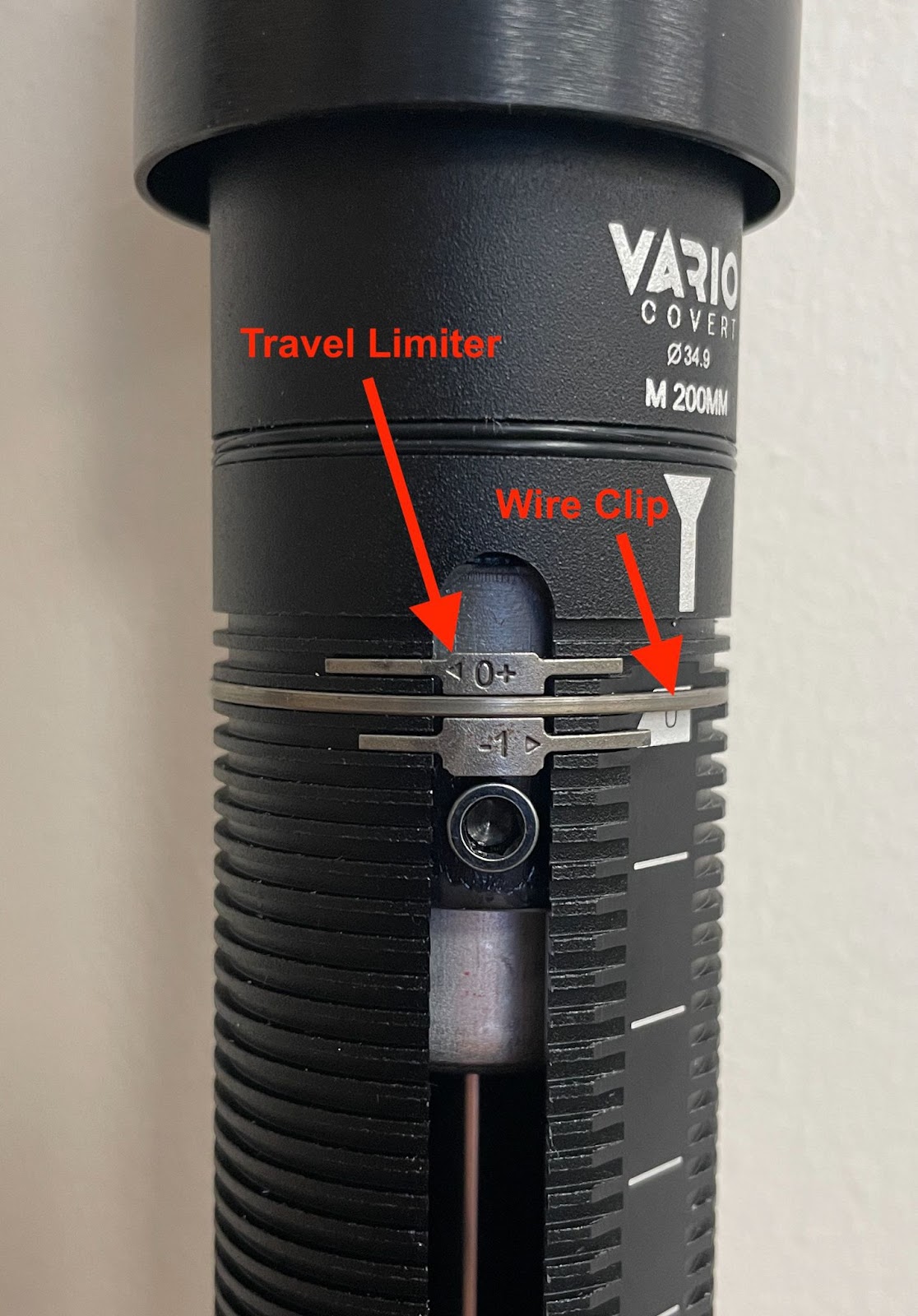
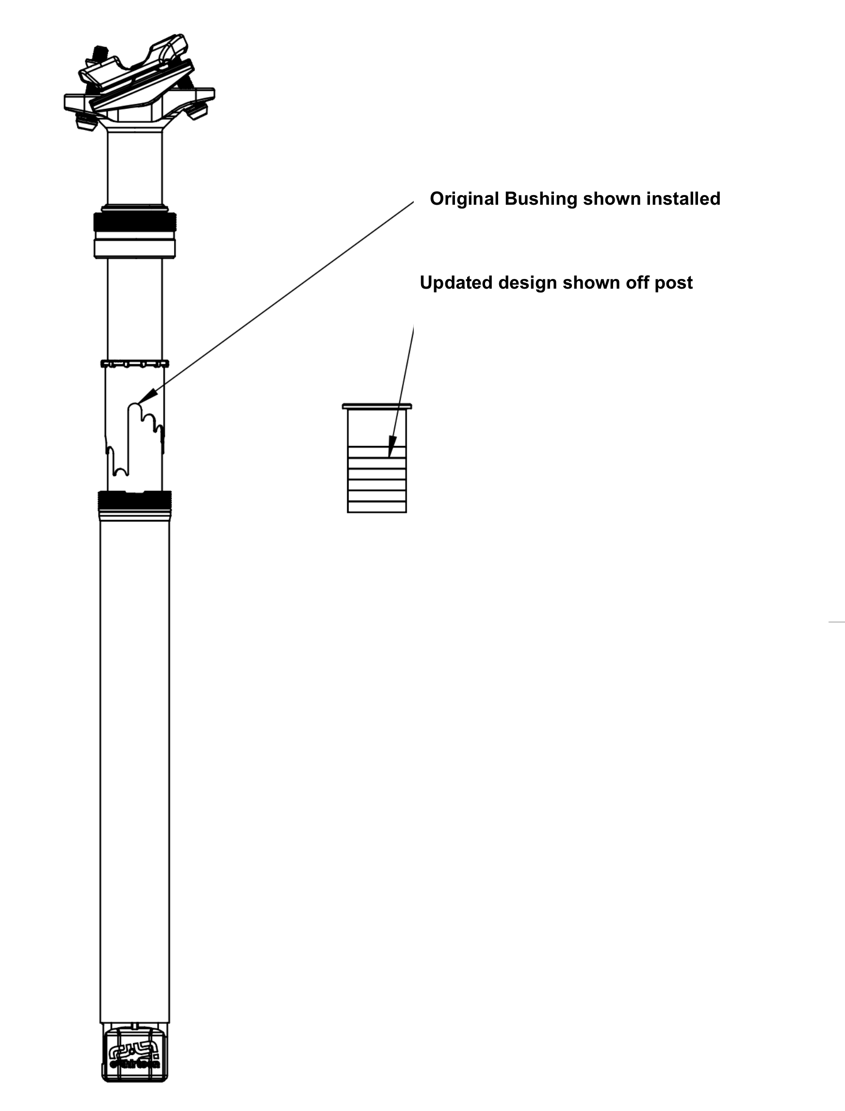
- e*thirteen’s SP30 Vario Covert dropper post is an integrated style of dropper post found stock as OEM equipment on certain Rotwild bike models sold in 2022 and 2023. The Vario Covert post uses a travel limiter clip to dictate the upper stop position. Early production versions used an o-ring to retain the travel limiter clip. In late 2022, the oring was changed to a wire clip.
Travel Limiter (shown with wire clip)
KEY POINTS
- Some early production versions were supplied with an oring which retained the travel limiter clip or a 1.0mm wire clip. Updated versions use a 1.2mm clip.
- Early versions utilizing an oring should be updated to use a 1.0mm wire clip. This clip is supplied at no charge from e*thirteen.
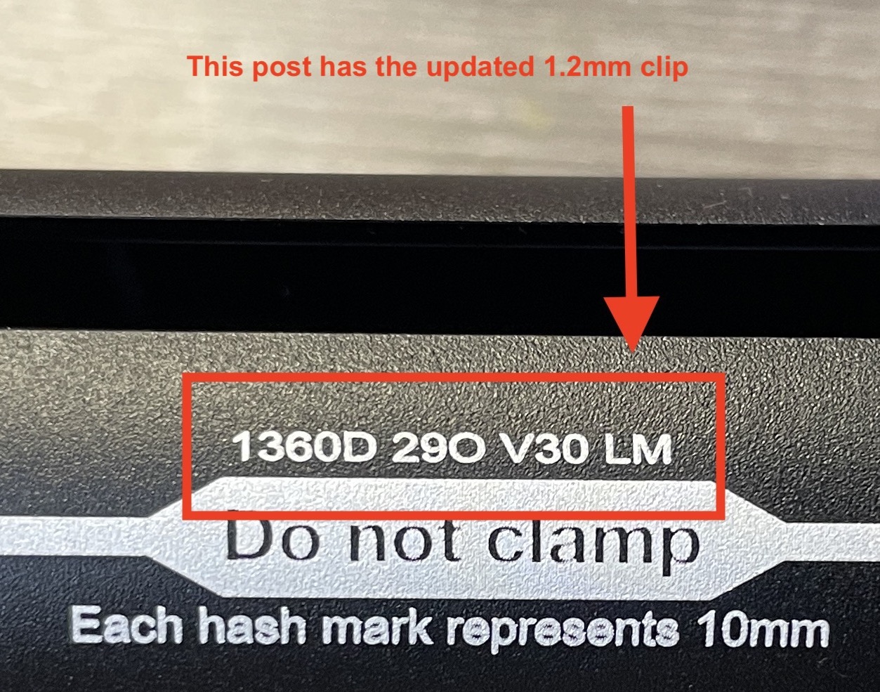
- The size of the clip can be identified by the production date code on the seatpost located here:
Seatposts using an oring or 1.0mm Clip will end with “SY”
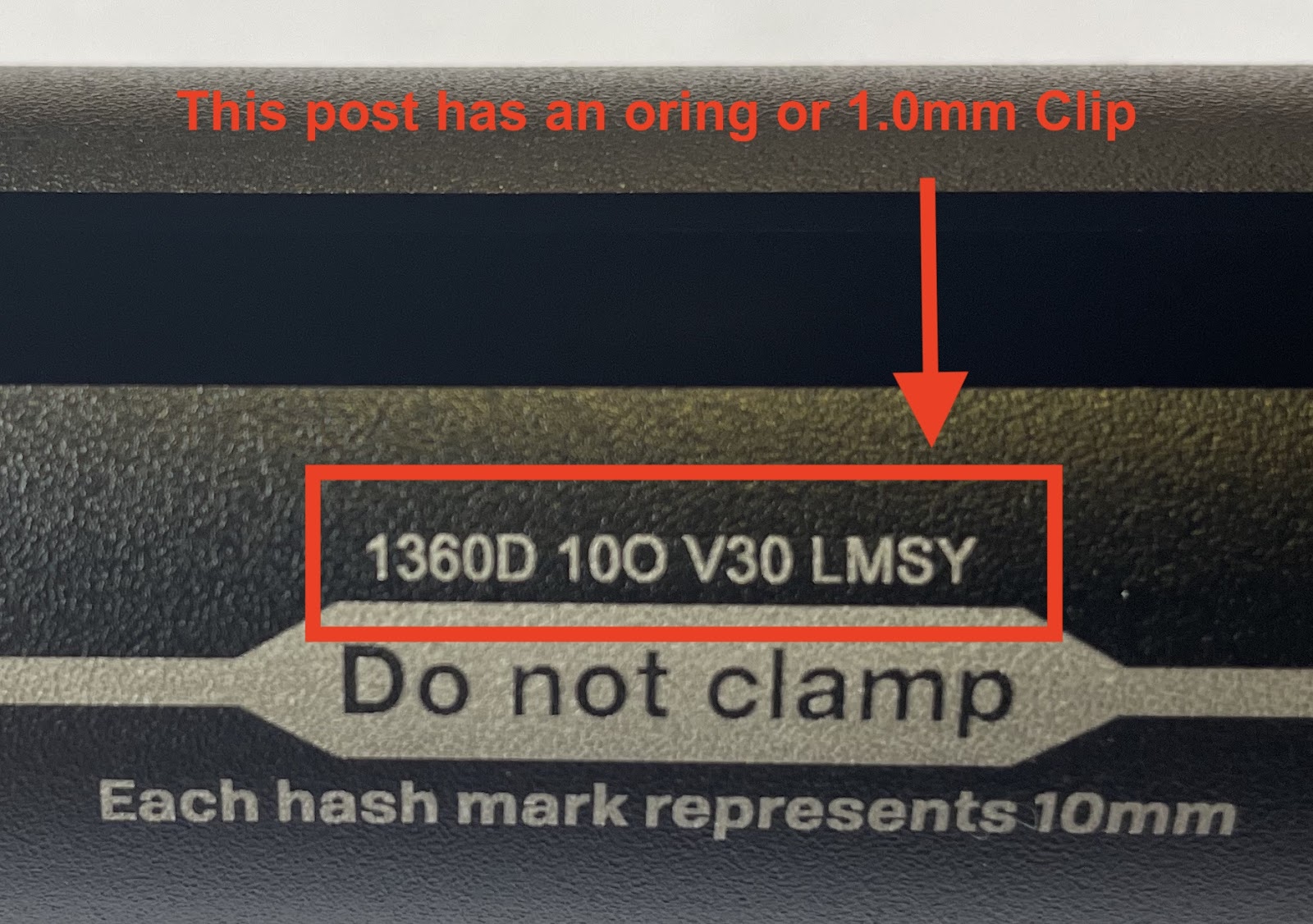
Seatposts using the updated 1.2mm clip will end with “LM”
-------
About e*thirteen:
When the cycling world calls for reliable performance solutions, e*thirteen responds.
A global organization of expert designers, engineers, developers, manufacturers, marketers, sales teams, and customer service players, e*thirteen builds bold, best in class bicycle solutions for today and tomorrow’s riders. After 20 years of building unique solutions across a variety of industry needs, e*thirteen is a leader providing bike retailers and riders high performing products with one goal – To stay true to the promise of fearless engineering for the best possible and most reliable ride.
TECHNICAL SERVICE BULLETIN #162
May 25,, 2022
Provided By: e*thirteen Technical & Engineering Dept.
Direct Questions To: Support@ethirteen.com
Download the full TSB here: TSB #162
Chain derailment on e*thirteen e*spec steel Bosch chainrings
THIS TECHNICAL SERVICE BULLETIN IS INTENDED FOR:
Distributors, Dealers & End-Users
PRODUCTS INCLUDED
- e*thirteen e*spec steel Bosch chainring
- 34t Part# CR4USA-100
- 36t Part# CR4USA-101
- 38t Part# CR4USA-102
BACKGROUND
- e*thirteen produces steel e*spec chainrings for Bosch Ebike motors with 34t, 36t, and 38t options.
- We have received reports in the field of chain derailment to the outboard side of the chainring when the motor is in higher power modes and the chain is in the small cogs of the cassette.
- e*thirteen believes chainline inconsistency originating at the spindle system or motor mount locations are the major contributing factors to this issue, combined with high torque (turbo) starts in a small cog. This issue has been reported across several bicycle brands using various manufacturers' chainrings.
RESOLUTION
- The issue may be remedied by moving the chainline outboard by installing a 1mm spacer behind the e*thirteen steel e*spec chainring on the spindle or a wider chainline ring. The spacer location is shown in the image below.
- e*thirteen will supply 1mm spacers free of charge to customers experiencing this problem. The spacer is not compatible with e*spec alloy chainrings, and no such issues have been reported with those rings.
- Request a 1mm spacer through your sales rep, e*thirteen dealer, or directly through our support page here: e*thirteen support request.
- Chainring lockring should be closely inspected and replaced if any signs of thread damage are present.
KEY POINTS
- Chain derailment issues are present in a small number of cases when using e*thirteen e*spec Steel chainrings on e-bikes equipped with Bosch motors.
- e*thirteen believes the root cause is a combination of chainline and motor torque in smaller cogs. Increasing chainline has proven to remedy the problem.
- e*thirteen will provide a spacer to increase chainline and a replacement chainring for customers experiencing the issue in the field.
- Find our user manual for Bosch e*spec crank and chainring install here: Bosch e*spec User Manual
- Install the 1mm spacer in the location shown in the diagram below:
About e*thirteen:
When the cycling world calls for reliable performance solutions, e*thirteen responds.
A global organization of expert designers, engineers, developers, manufacturers, marketers, sales teams, and customer service players, e*thirteen builds bold, best in class bicycle solutions for today and tomorrow’s riders. After 20 years of building unique solutions across a variety of industry needs, e*thirteen is a leader providing bike retailers and riders high performing products with one goal – To stay true to the promise of fearless engineering for the best possible and most reliable ride.
TECHNICAL SERVICE BULLETIN #161
May 10, 2022
Provided By: e*thirteen Technical & Engineering Dept.
Direct Questions To: support@ethirteen.com
Download full TSB here: TSB #161
UPDATE FOR HELIX RACE CASSETTE USE ON EBIKES
THIS TECHNICAL SERVICE BULLETIN IS INTENDED FOR:
Distributors, Dealers & End-Users
PRODUCTS INCLUDED
- e*thirteen Helix Race 11-Speed Cassettes
- 9/46T part #s FW2HRA-106, FW2HRA-107, FW2URA-113
- e*thirteen Helix Race 12-Speed Cassettes
- 9/45T, part #s FW2HRA-100, FW2HRA-101
- 9/50T, part #s FW2HRA-102, FW2HRA-103, FW2HRA-104, FW2HRA-105, FW2URA-112
BACKGROUND
- e*thirteen Helix Race Cassettes were released in 2021 with focused improvements on shift quality, weight reduction and drivetrain brand cross-compatibility.
- Helix Race cassettes were developed for MTB use and not recommended for EMTBs at that time.
- For 2022, updates were made to Helix cassettes to strengthen key loading points to ensure ebike compatibility and e*thirteen now approves Helix Race cassettes for use on EMTBs.
KEY POINTS
- Product:
- While still not considered our “e*spec rated” cassette, riders can now use Helix Race cassettes on EMTBs and retain the full benefits of their robust e*thirteen product warranty.
- The Helix Plus 9/50 12s cassette (Part# FW2HPA-100) and TRS+ 9/46 11s cassette (Part# FW2TPA-101) are our “e*spec rated” cassettes and are the best option for general EMTB use.
_____
About e*thirteen:
When the cycling world calls for reliable performance solutions, e*thirteen responds.
A global organization of expert designers, engineers, developers, manufactures, marketers, sales teams, and customer service players, e*thirteen is dedicated to building bold,“best in class“ bicycle solutions for today and tomorrow’s riders. After 20 years of building unique solutions across a variety of industry needs, e*thirteen is a leader providing bike retailers and riders high performing products with one goal – To stay true to the promise of fearless engineering for the best possible and most reliable ride.
TECHNICAL SERVICE BULLETIN #160
May 17, 2022
Provided By: e*thirteen Technical & Engineering Dept.
Direct Questions To: support@ethirteen.com
Download full TSB here: TSB #160
INTRODUCTION AND CHANGEOVER TO GEN 2 7 SPEED CASSETTE
THIS TECHNICAL SERVICE BULLETIN IS INTENDED FOR:
Distributors, dealers & end-users
PRODUCT INCLUDED
- e*thirteen LG1 DH Wheels and hubs using 7s integrated driver.
- e*thirteen part numbers: WH3LRA-105, WH3LRA-108, WH4LPA-109, WH4LPA-110, HB3LRA-100, FWS10-104.
PRODUCT NOT INCLUDED
- e*thirteen wheels and hubs using traditional style drivers - XD™, Microspline™, and HG™
BACKGROUND
- e*thirteen’s Gen 1 Integrated 7s DH 9-21t cassette was released 5+ years ago to allow for wider hub flange spacing on DH rear wheels resulting in stronger and more reliable rear wheels. The incorporation of the 9T cog also allowed for DH bikes to use smaller front chainrings, permitting improved ground clearance and reduced likelihood of ring damage.
- In Q2 of 2022, e*thirteen’s Gen 2 Integrated 7s cassette is being released and will begin shipping on complete wheels, and as a service part for replacement. There are updates to the gearing, finish and shifting.
KEY POINTS
- Product:
- Gearing updates: Gen 1 7s driver used a 9-21 gearing. Based on feedback from our world cup athletes, the Gen 2 7s driver has been updated to a 9-24t gearing. Our racers wanted a wider gearing range, but needed to maintain the tight gearing jumps on the high end of the cassette for their race runs.
- Shift quality improvements: Notable shift quality improvements have been made to the new 9-24 7s driver which incorporates shift features found on our highly acclaimed Helix Cassettes.
- Finishing improvements: Gen 1 7s cassettes used a black oxide finish. Gen 2 7s driver uses nickel plating for improved durability, corrosion resistance and a more technical appearance.
- SKU Changeover:
- Complete wheel & hub SKUs using our 7s cassette will not change
- Gen 2 cassettes will be a running change on complete wheels/hubs
- Service part SKUs will change:
- Old Gen 1 7s cassette: FWS10-104 is discontinued and no longer available.
- New Gen 2 7s cassette: FWS20-121 - e*thirteen | 7sp cassette | fits LG1 7sp rear hubs only | 9-24T | silver / EAN 4711280340613
- Complete wheel & hub SKUs using our 7s cassette will not change
-------
About e*thirteen:
When the cycling world calls for reliable performance solutions, e*thirteen responds.
A global organization of expert designers, engineers, developers, manufacturers, marketers, sales teams, and customer service players, e*thirteen builds bold, best in class bicycle solutions for today and tomorrow’s riders. After 20 years of building unique solutions across a variety of industry needs, e*thirteen is a leader providing bike retailers and riders high performing products with one goal – To stay true to the promise of fearless engineering for the best possible and most reliable ride.
TECHNICAL SERVICE BULLETIN #159
February 8, 2022
Provided By: e*thirteen Technical & Engineering Dept.
Direct Questions To: support@ethirteen.com
Download full TSB here: TSB 159
SRAM™ GX™ XD 1275 cassette bushing fit on e*thirteen SL XD™ driver bearing
THIS TECHNICAL SERVICE BULLETIN IS INTENDED FOR:
Distributors, dealers & end-users
PRODUCT INCLUDED
- e*thirteen XD™ drivers with exposed outboard bearing found on SL hubs with alloy axles when used in conjunction with SRAM™ GX XD™ 1275 cassettes
PRODUCT NOT INCLUDED
- e*thirteen XD™ drivers with exposed bearing when used in conjunction with any cassette other than SRAM™ GX™ XD™ 1275 cassettes
- e*thirteen HG™ and Microspline™ drivers
- e*thirteen SL XD drivers used on hubs with steel axles.
BACKGROUND
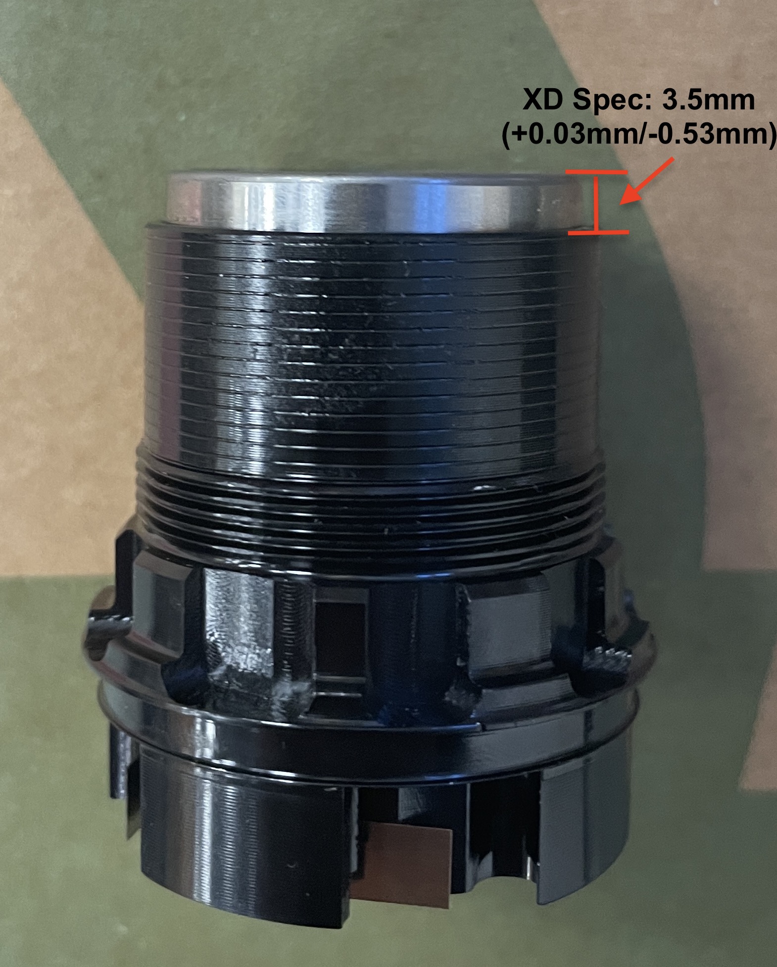
- e*thirteen and other industry companies license the XD™ driver standard from SRAM™ and design XD™ drivers in accordance with that standard. The XD™ Standard can be found here: https://www.xddriverbody.com/. Specifications of the standard include a partially exposed driver bearing at the end of the freehub body.
- Late 2021, e*thirteen was made aware of issues created when demounting SRAM™ GX™ XG 1275 cassettes installed on our SL XD™ drivers, when used in conjunction with alloy hub axles. SRAM™ cassettes incorporate a plastic bushing which interfaces with the exposed bearing on the end of the XD™ driver. The bushing found on the SRAM™ GX™ XG-1275 cassette is a tighter fit than ones found on other SRAM™ cassettes and can extract the bearing from the shell of the driver during the cassette removal process.
RECOMMENDED ACTION
Because the integrity of the bearing press in the driver is not impacted by bearing extraction from the cassette, YOU CAN simply press the bearing back in place in the driver with a small amount of Loctite 242 (or similar retaining compound) and reinstall the cassette using normal install procedure.
The correct spec for bearing protrusion with the SRAM™ XD™ Driver standard is 3.5mm +0.03mm/-0.53mm. A hard stop will be felt during the press operation once full insertion has been made.
-------
About e*thirteen:
When the cycling world calls for reliable performance solutions, e*thirteen responds.
A global organization of expert designers, engineers, developers, manufactures, marketers, sales teams, and customer service players, e*thirteen is dedicated to building bold,“best in class“ bicycle solutions for today and tomorrow’s riders. After 20 years of building unique solutions across a variety of industry needs, e*thirteen is a leader providing bike retailers and riders high performing products with one goal – To stay true to the promise of fearless engineering for the best possible and most reliable ride.
TECHNICAL SERVICE BULLETIN #158
November, 2021
Provided By: e*thirteen Technical & Engineering Dept.
Direct Questions To: support@ethirteen.com
Download the full TSB here.
TECHNICAL SERVICE BULLETIN #158 - VARIO SEATPOST TRAVEL ADJUST UPDATE
THIS TECHNICAL SERVICE BULLETIN IS INTENDED FOR:
e*thirteen distributors, dealers & end-users
PRODUCT INCLUDED
e*thirteen Vario Seatpost - All lengths and sizes
BACKGROUND
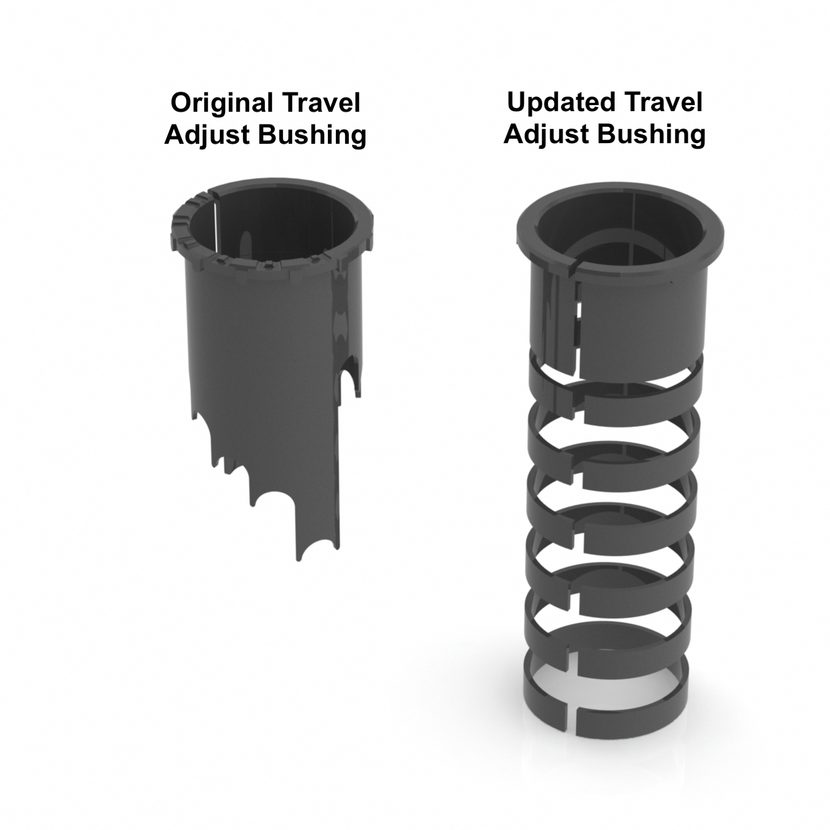
e*thirteen Vario droppers were released in 2020 and used a stepped bushing to allow tool free travel changes by simply rotating the bushing.
Around the time the Vario was released, e*thirteen learned of a patent filed in Taiwan which detailed a similar method of achieving travel adjustment in a seatpost. That application was subsequently granted, so out of respect for that parties invention e*thirteen is changing the method used to achieve travel adjustments of the Vario seatposts.
RESOLUTION
Beginning in November 2021, Vario Seatposts began shipping with an updated travel adjust bushing assembly which replaces the original stepped assembly. The new assembly consists of a main bushing and a stack of 5mm shims which allow for the same level of adjustability as the original bushing simply by adding or removing shims. This process continues to be a tool-free operation and has no impact on Vario product specifications beyond the slight procedural change for adjusting the travel.
The adjustable travel bushing will continue to be supplied in our Vario Seatpost Refresh kit and can be purchased as a service item in service item: SPS20-103 - e*thirteen | Vario Infinite Dropper Rebuild Kit | Incl. Collar, Seal, Adjustable Travel Bushing, Keys, Lower Bushing | Fits All Vario Posts
Owners manuals and technical support documents will be updated to show both travel adjust options.
See below for images of original and updated bushing
RECOMMENDED ACTION
End users: No action needed.
Distributors & Dealers: Inform appropriate technical and sales entities within your company about the update.
About e*thirteen:
When the cycling world calls for reliable performance solutions, e*thirteen responds.
A global organization of expert designers, engineers, developers, manufactures, marketers, sales teams, and customer service players, e*thirteen is dedicated to building bold,“best in class“ bicycle solutions for today and tomorrow’s riders. After 20 years of building unique solutions across a variety of industry needs, e*thirteen is a leader providing bike retailers and riders high performing products with one goal – To stay true to the promise of fearless engineering for the best possible and mostreliable ride.
TECHNICAL SERVICE BULLETIN #157
Shimano™ EP8 Spindle Inspection in Conjunction with e*thirteen e*spec Cranks
Provided By: e*thirteen Technical & Engineering Dept.
Direct Questions To: support@ethirteen.com
Download Full Technical Service Bulletin: TSB 157
--------
THIS TECHNICAL SERVICE BULLETIN IS INTENDED FOR:
e*thirteen OEM’s, assembly factories, distributors, dealers & end-users
PRODUCTS INCLUDED:
e*thirteen e*spec cranks used on Shimano™ EP8 (DU-EP800) Motors .
Part Numbers & Descriptions
| CS3EPA-100 | e*spec Plus Crank | Shimano™ EP8 | 165mm |
| CS3EPA-101 | e*spec Plus Crank | Shimano™ EP8 | 170mm |
| CS3EPA-102 | e*spec Plus Crank | Shimano™ EP8 | 175mm |
| CS3EPA-103 | e*spec Plus Crank | Shimano™ EP8 | 160mm |
| CS3EPM-100 | e*spec Plus Crank | 160mm | Shimano™ EP800 | 178Q |
| CS3EPM-101 | e*spec Plus Crank | 165mm | Shimano™ EP800 | 178Q |
| CS3EPM-102 | e*spec Plus Crank | 170mm | Shimano™ EP800 | 178Q |
| CS3EPM-111 | e*spec Plus Crank | 165mm | Shimano™ EP800 | 177Q | Intense MX |
| CS3ERM-101 | e*spec Plus Crank | Shimano™ EP8 | 165mm | Q 177 |
| CS3ERM-102 | e*spec Plus Crank | Shimano™ EP8 | 165mm | Q 177 |
PRODUCTS NOT INCLUDED:
e*thirteen e*spec cranks used on Shimano™ E7000 or E8000 motors.
Note: While identical e*thirteen e*spec crank arms are used across Shimano™ E7000, E8000, and EP8 (DU-EP800) motors, spindle failures have only been reported to e*thirteen on EP8 (DU-EP800) motors -- therefore Shimano™ E7000 or E8000 motors are not included in this TSB.
BACKGROUND
- e*spec alloy and carbon cranks were developed specifically for Shimano™ ebike motors and sold via OEM and aftermarket channels in 2020 & 2021.
- March 2021, e*thirteen was made aware of Shimano™ EP8 spindle failures when used in conjunction with a number of different brands’ cranks, including the e*thirteen e*spec cranks.
- e*thirteen took immediate action to diagnose the issue with extensive 3rd party lab testing and metallurgical analysis to understand the root cause.
- e*thirteen’s analysis suggests that some Shimano™ EP8 spindles may have manufacturing defects which over time, can develop into cracks with use and exposure to the elements.
- This Technical Service Bulletin, #157, suggests a safety inspection to verify the motor spindle integrity when these cranks are used in conjunction with the EP8 motor.
CURRENT STATUS
Currently e*thirteen cranks pass and exceed all bicycle testing standards applicable to these components (ISO, EN, DIN) -- e*thirteen is confident that our cranks are not the source of the issue.
RECOMMENDED ACTION
e*thirteen recommends inspecting Shimano™ EP8 motor spindles to ensure no cracks are present before riding any EP8 equipped bike again and in doing so have provided a step by step process for doing this with images and instructions below.
The inspection is done by removing the crank arms, thoroughly cleaning the spindle, and closely inspecting the area located around the hole drilled through the spindle in the splined location.
Please see written instructions with visuals below. If any help is needed, please contact the e*thirteen support team at support@ethirteen.com.
While e*thirteen does not foresee any issues with e*thirteen cranks, we stand behind our products and have warranty policies in place for our products. Please view our warranty policy and request form HERE.
--------
INSTRUCTIONS FOR ARM REMOVAL PROCEDURE
Note: Procedure is the same for left and right arms and should be performed on both
STEP 1 - LOOSEN PINCH BOLTS
Loosen counterclockwise both 5mm pinch bolts which attach the crank arm to the spindle. Ensure they are fully loose by alternating bolts until a gap between the head of the bolt and crank arm is visible.
STEP 2 - REMOVE PRELOAD CAP
Using a 5mm hex key, loosen counterclockwise and remove the preload cap.
STEP 3 - REMOVE ARMS AND CLEAN MOTOR SPINDLE WITH DEGREASER
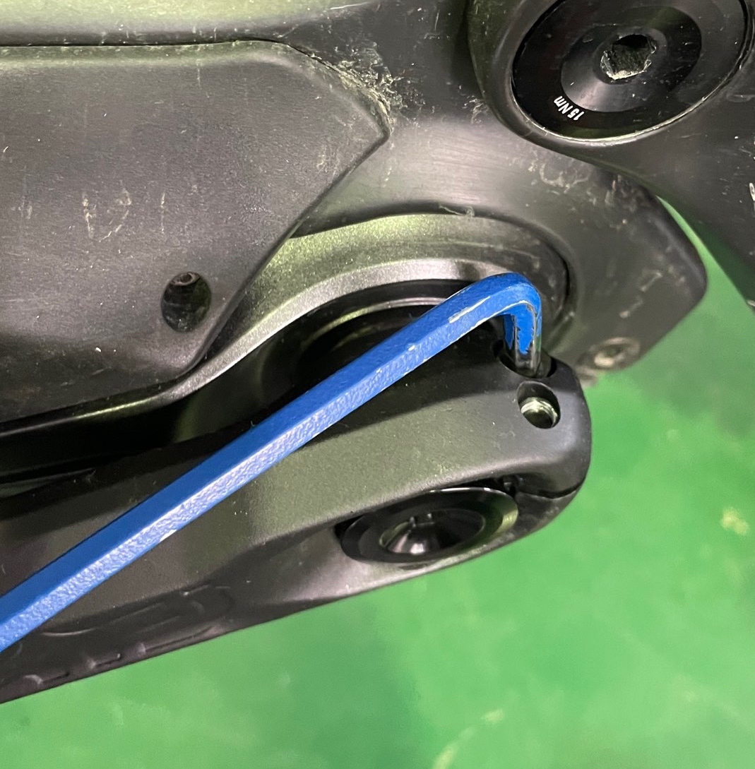
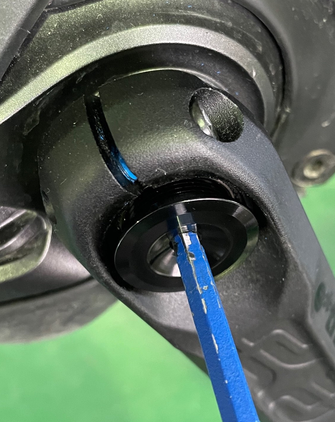
STEP 4 - CLOSELY INSPECT THE EXPOSED SPINDLE, PAYING PARTICULAR ATTENTION TO THE AREA AROUND THE CROSS-DRILLED HOLE. INSPECT BOTH INSIDE AND OUTSIDE THE SPINDLE (Using your smartphone camera and zooming in can give additional clarity)
INSIDE VIEW
OUTSIDE VIEW
Note: Trough/groove marks pictured on the wide spline tooth and elsewhere on the spindle are manufacturing marks present from the factory. These marks are inconsistent, and may not necessarily be present on all spindles!
STEP 5 - REINSTALL OR CONTACT THE APPROPRIATE PARTY FOR REPLACEMENT
- If no crack is present, move onto the arm install procedure below.
- If crack is present or you are unsure, contact your Bicycle Manufacturer or local Shimano Service Center for further instructions.
--------
ARM INSTALL PROCEDURE - Procedure is the same for left and right arms and should be performed on both.
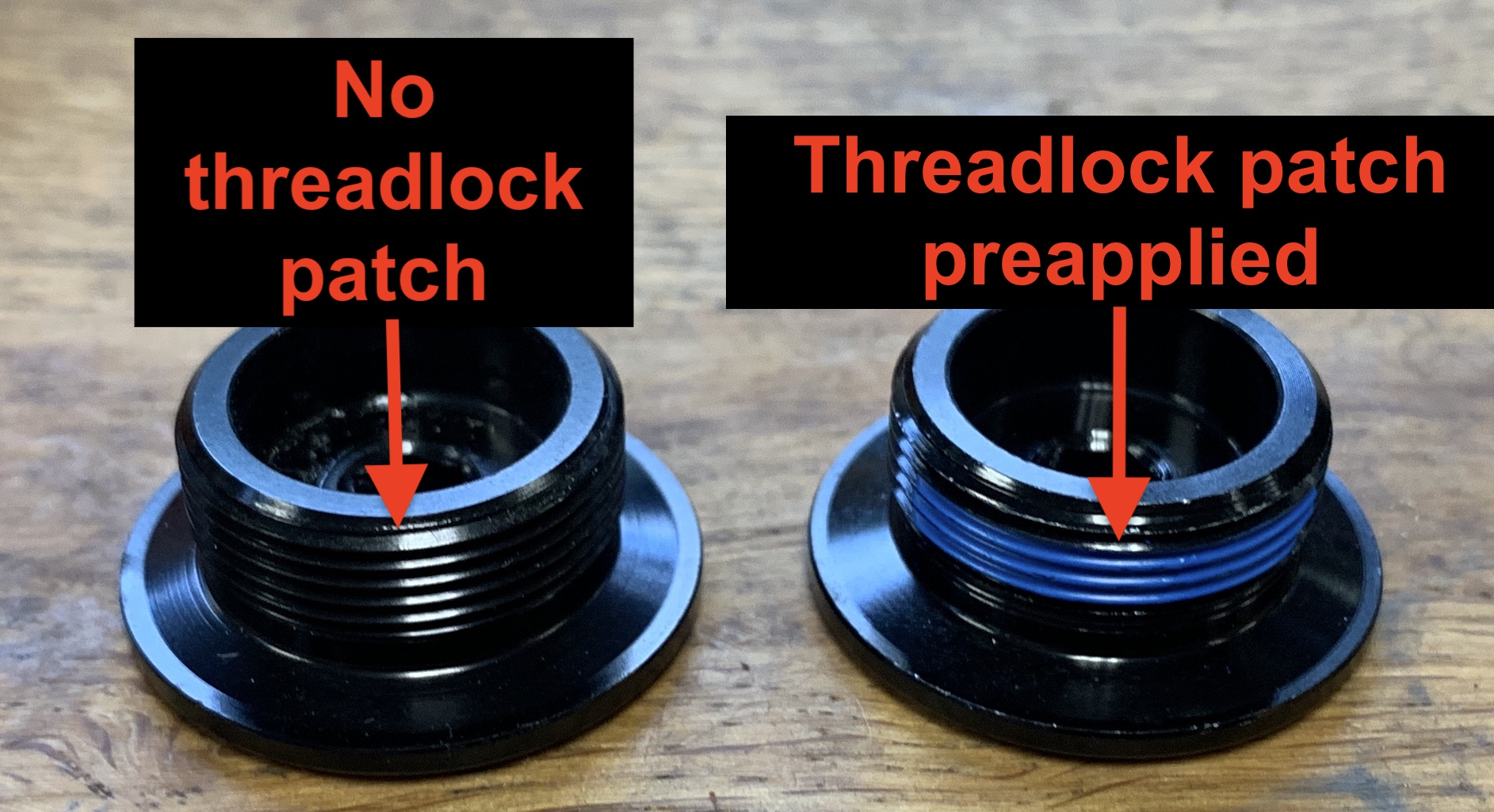
STEP 1 - VERIFY PRELOAD CAPS HAVE A PRE-APPLIED THREADLOCKER PATCH.
Note: Preload bolts may appear visually different than shown in photo.
If threadlock patch is present, move on to step 2. If there is no threadlocker patch, move to the next point.
If preload cap has no threadlock patch pre applied, Clean inner and outer threads and apply 1 drop of Loctite 242 or similar light/medium threadlocker compound to the threads on the preload cap.
Alternatively, you can contact e*thirteen to be supplied with a preload caps with pre applied threadlocker.
STEP 2 - INSTALL ARMS ONTO SPINDLE
Note left vs right arms and also orientation of the pinch clamp relative to the hole in the spindle. The crank arms should be installed on the spindle with pinch clamp at 180 degrees from the hole in the spindle as shown in image below.
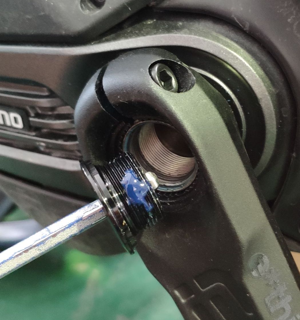
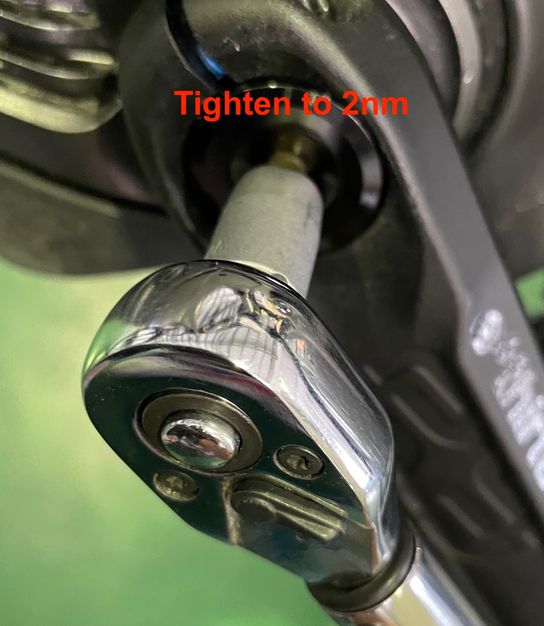
STEP 3 - REINSTALL PRELOAD CAP AND TORQUE FASTENERS TO SPEC
Install and tighten preload cap to 2Nm
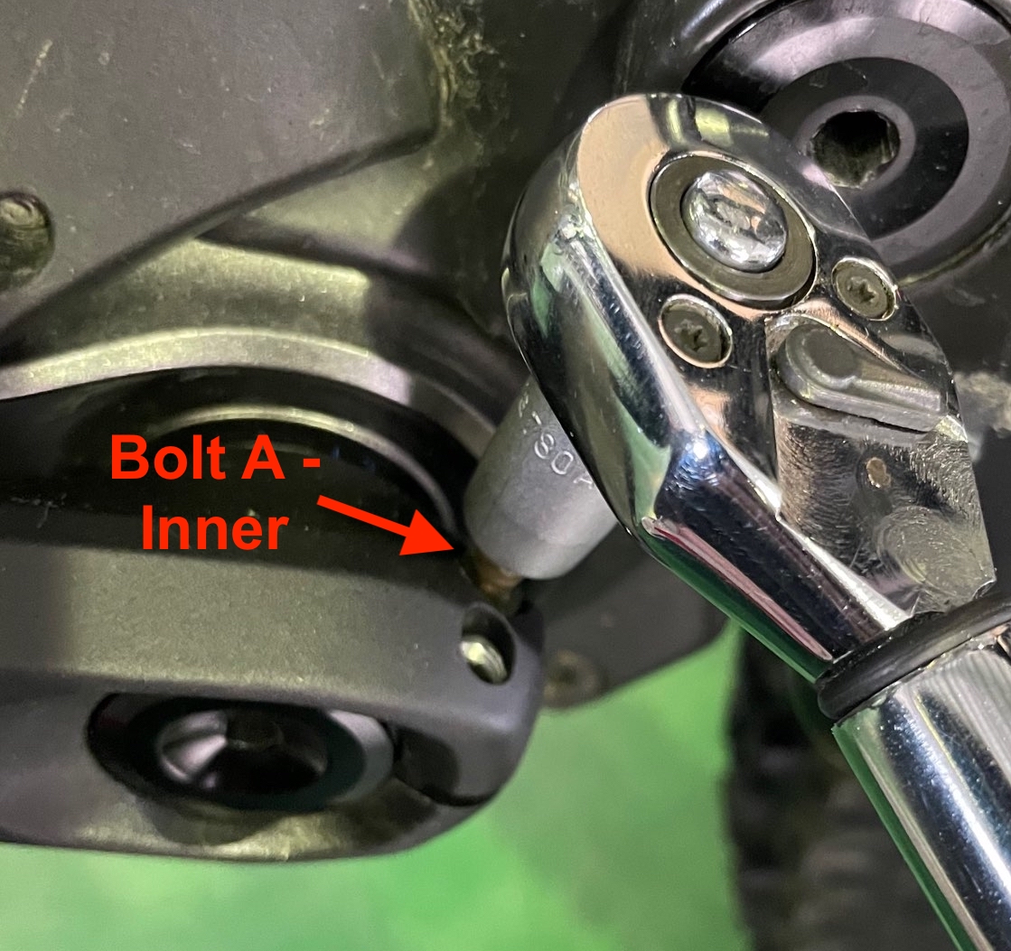
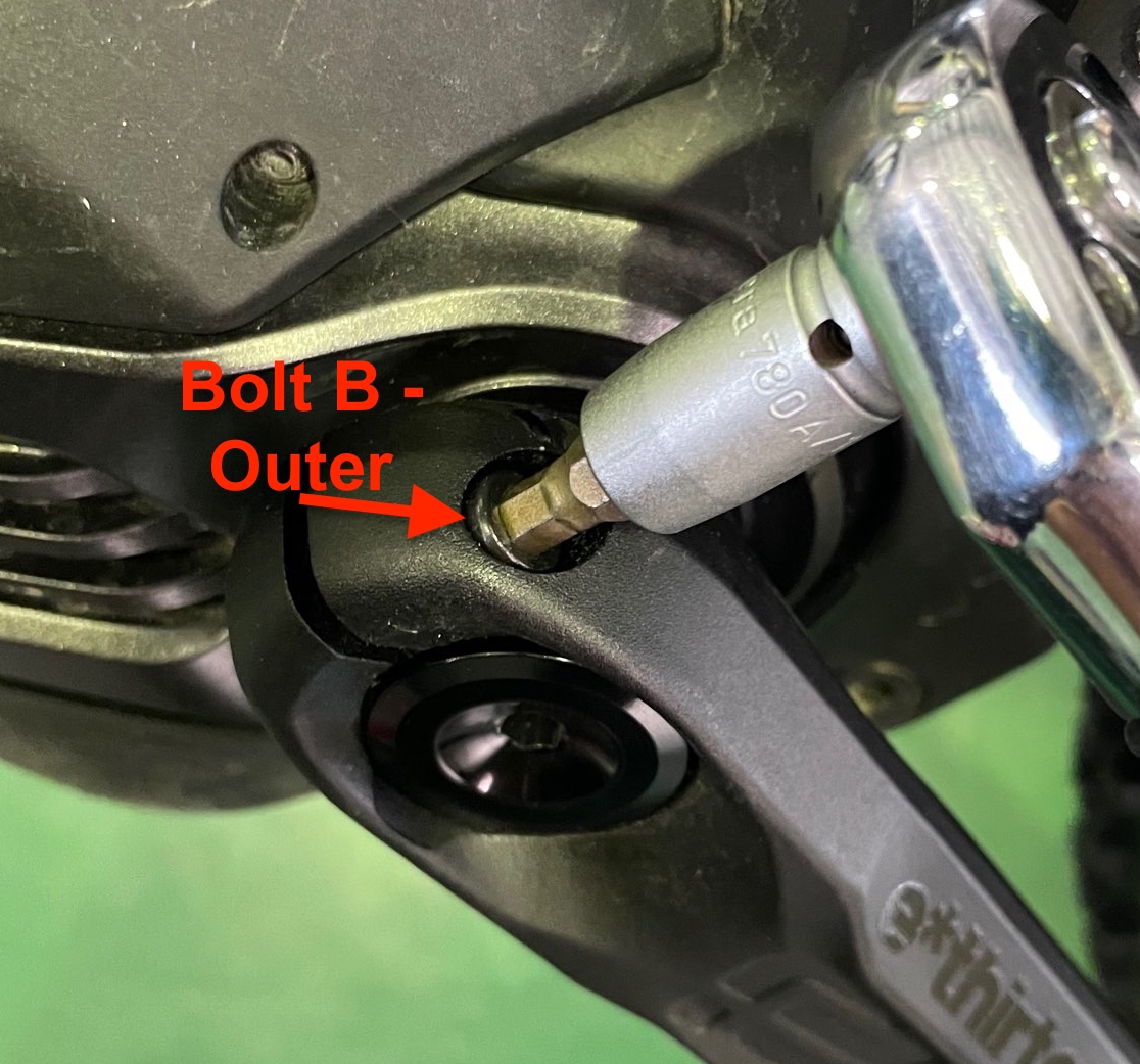
Using a torque wrench, tighten crankarm pinch bolts using an alternating sequence until both bolts reach 14Nm. You will do this (2) times starting with the inside bolt (a) then the outside bolt (b), then repeat. Sequence = (a)(b)(a)(b)
STEP 4 - REPEAT PROCEDURE ON OTHER ARM
STEP 5 - RECHECK PINCHBOLT TIGHTNESS AFTER 1-2 RIDES TO ENSURE 14Nm TORQUE ON PINCHBOLTS
--------
About e*thirteen
When the cycling world calls for reliable performance solutions, e*thirteen responds.
A global organization of expert designers, engineers, developers, manufactures, marketers, sales teams, and customer service players, e*thirteen is dedicated to building bold ,“best in class“ bicycle solutions for today and tomorrow’s riders. After 20 years of building unique solutions across a variety of industry needs, e*thirteen is a leader providing bike retailers and riders high performing products with one goal – To stay true to the promise of fearless engineering for the best possible and most reliable ride.
TECHNICAL SERVICE BULLETIN #156.2
e*spec Shimano™ alloy crank tech update
Product(s) included: e*thirteen e*spec Shimano EP8 alloy cranks.
Abstract
e*spec Shimano EP8/EP800 alloy cranks were developed specifically for Shimano™ ebike motors and sold via OEM and aftermarket channels in 2020 & 2021. This TSB highlights install torque updates and additional measures we have taken to address the issue highlighted below.
Issue
We have had reports of crank arm preload caps from affected cranks loosening up and falling off. If crank pinch bolts, which fix the arm to the axle, are not tightened to spec or properly tightened, it is possible that lack of cap and incorrect installation torque and/or install technique could lead to the arm loosening.
This situation has been misinterpreted by some to mean there is a failure of one or more system components. That is not the case, but all cranks should be checked for proper tightness before riding, and initial installations procedures should be updated.
Solution
- Threadlocker patch:
- Early production preload caps did not incorporate a threadlocker patch to prevent loosening in the case that the cap was not properly tightened upon install. A threadlocker patch is now being used on all preload caps. Customers with caps lacking threadlocker patch can use light/medium strength threadlocker such as Loctite 222 or Loctite 242; or contact e*thirteen support for a replacement cap.
- Torque specification updates:
- Original torque specification: Preload cap: 1Nm / Pinch bolts: 12-14Nm.*
- Updated torque spec: Preload cap 2Nm / Pinch bolts: 14Nm.*
*Correct tightening procedure is critical. Please reference directions below
- Inner seal removal:
- The seal found at the inner face of the crank should be removed from the assembly. This avoids potential false torque readings and provides an additional 1mm of interface between the crank and spindle.
- Note: Removing inner seal must be done in conjunction with using the e*thirteen preload cap. Using non-e*thirteen preload caps may result in the cap bottoming out on the spindle before preloading the crank.
Arm Install Orientation
Verify crank arms are installed on the spindle with pinch clamp at 180 degrees from the hole in the spindle as shown in image below.
Arm Tightening Procedure
*Note: Procedure is the same for left and right arms and should be performed on both.*
- Step 1 - Verify if preload cap needs loctite applied, and apply if necessary.
- Loosen counterclockwise both 5mm pinch bolts which attach the crank arm to the spindle. Ensure they are fully loose by alternating bolts until a gap between the head of the bolt and crank arm is visible.
- Step 2 - Identify if preload caps have a pre-applied threadlocker patch and apply if necessary.
- 2a - Using a 5mm hex key, loosen counterclockwise and remove the preload cap.
-
- 2b - If threadlock patch is present, move on to step 3. If there is no threadlocker patch, move onto point 2c.
- 2c - If preload cap has no threadlock patch pre applied:
- Clean inner and outer threads and apply 1 drop of Loctite 242 or similar light/medium threadlocker compound to the threads on the preload cap
- or, Contact e*thirteen to be supplied with a preload caps with pre applied threadlocker
- Step 3 - Reinstall preload cap and torque fasteners to spec.
-
- 3a - Install and tighten preload cap to 2nm
- 3b - Using a torque wrench, tighten crankarm pinch bolts using an alternating sequence until both bolts reach 14nm. You will do this (2) times starting with the inside bolt (a) then the outside bolt (b), then repeat. Sequence = (a)(b)(a)(b)
- Step 4 - Repeat procedure on other arm.
- Step 5 - Recheck pinch bolt tightness after 1-2 rides to ensure 14nm torque on pinch bolts.
Click below in download
Click below to download the PDF
Click below to download the PDF
Click below to download the PDF